MAKEWERKS
Spool Hub Design
This spool hub is used to mount a filament spool to a stand and allow it to rotate smoothly about its axis. The three main functional requirements for the spool hub are as follows.
- Fit a range of spool widths
- Fit a range of spool hole diameters
- Allow for smooth rotary motion
Also, because this was one of my first functional print designs for Fused Filament Fabrication (FFF), I wanted to start to understand the strengths and limits of this 3D printing process and how designs should take them into account. So, I added the following as a fourth design requirement.
- Fully 3D printed (no metal fasteners, rods, etc)
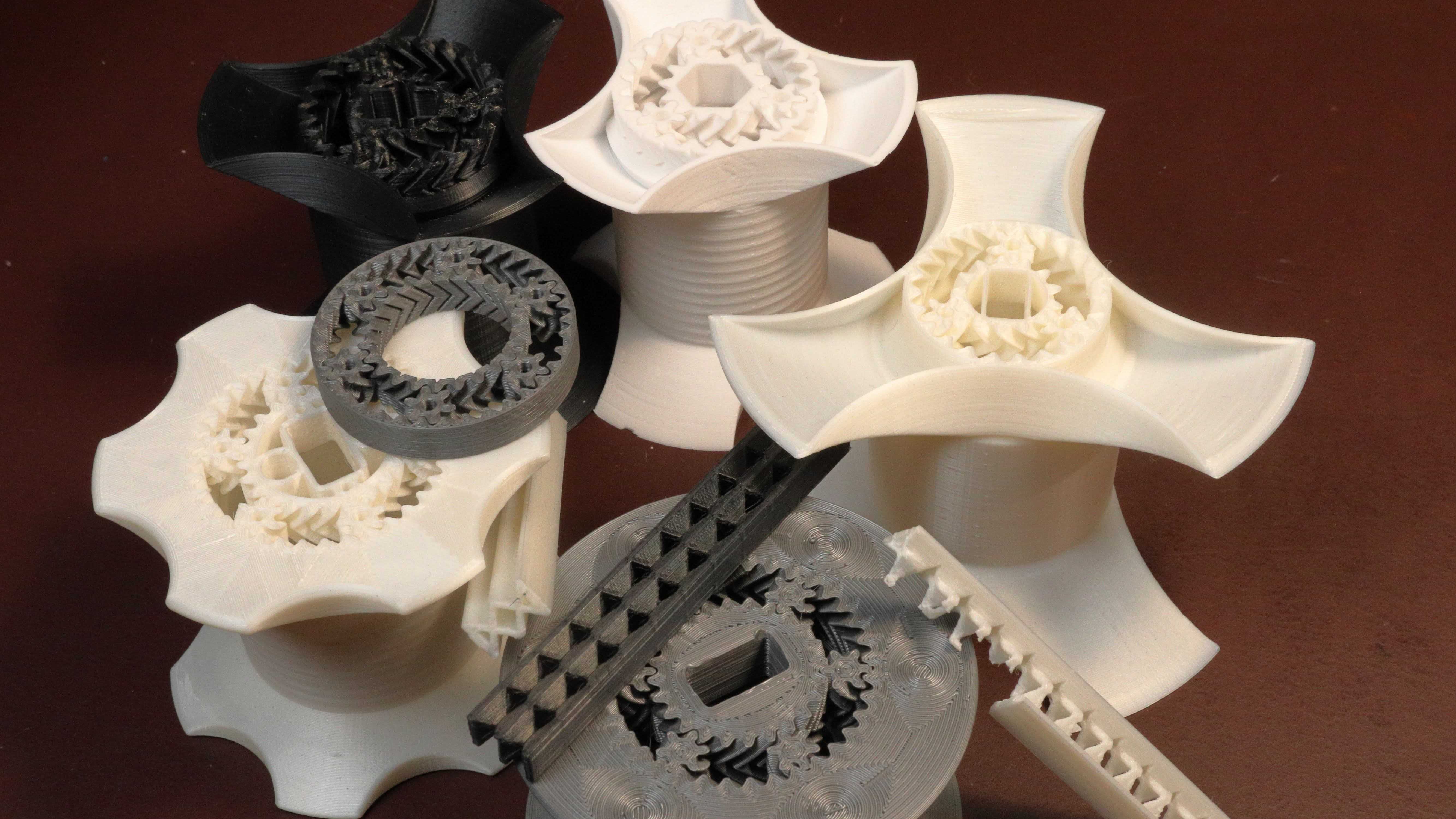
The current spool hub design, shown below, combines tapered flanges, big threads, a vase mode printed spring-axle and print-in-place helical gear bearings. It remains one of my favorite functional prints because the simplicity resulting from the requirement to be fully 3D printed has resulted in, I think, an elegant solution. The print-in-place bearings are very satisfying to use and provide an example of a part that cannot be produced in one piece through “traditional” subtractive manufacturing methods.
Spool Widths and Hole Diameters
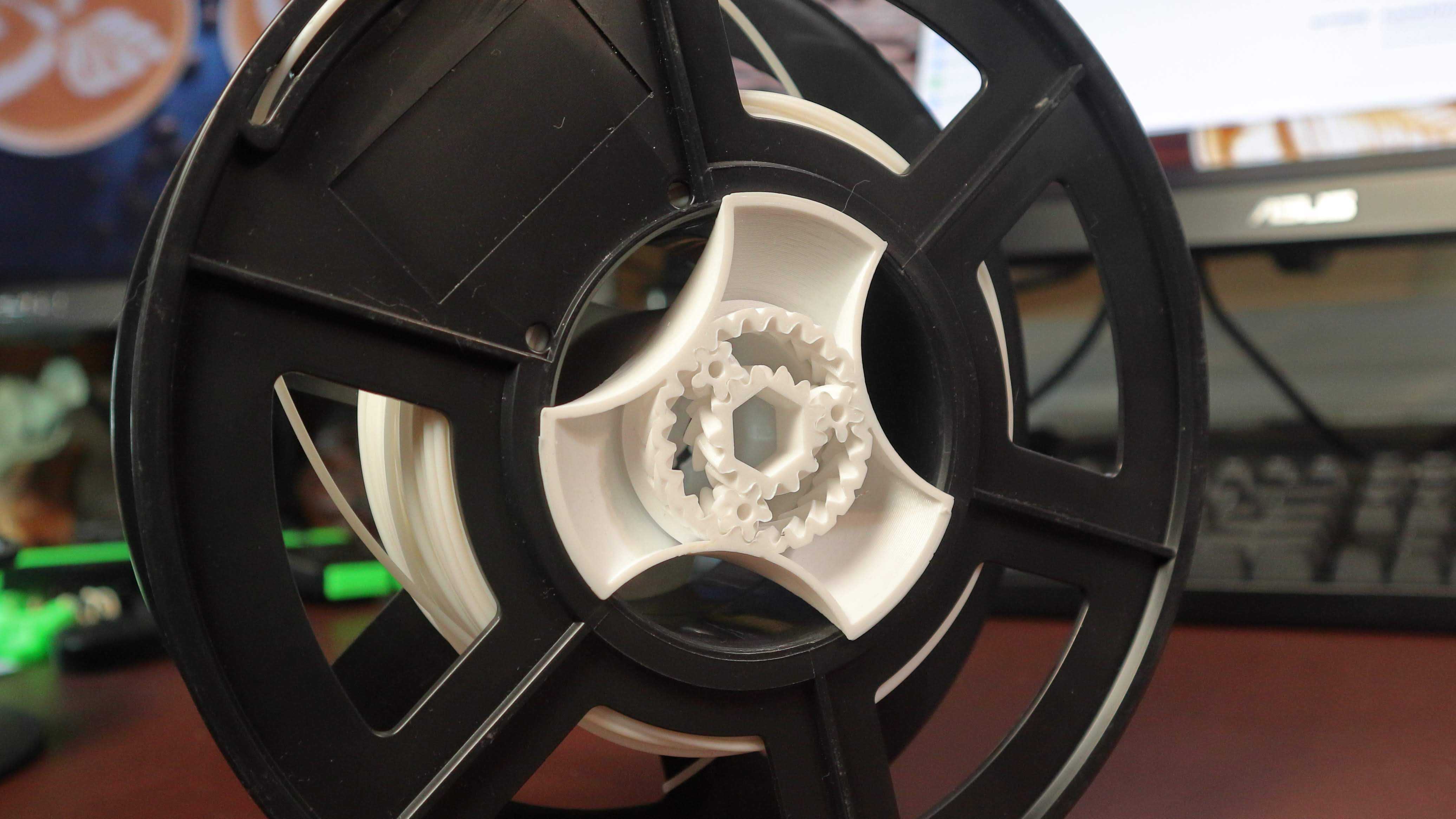
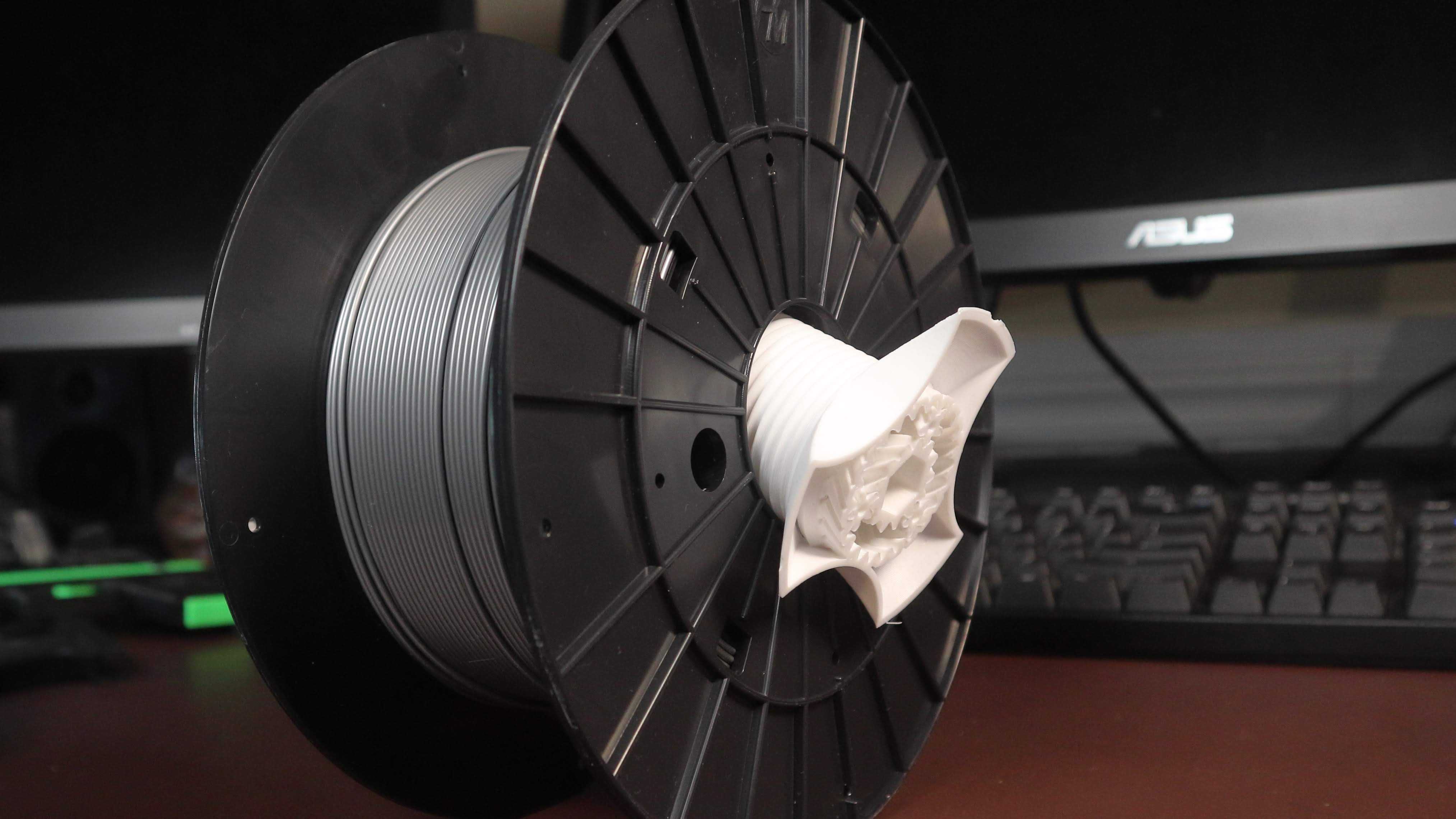
The spool hub design uses a combination of threads and conic flanges to provide the fit to spools with a range of widths and hole diameters. The two end pieces of the spool hub pass through the center-hole of a filament spool and screw together, clamping the spool between them. The spool hub’s tapered flanges engage the edge of the spool center hole and self-center as the threads are tightened to provide the clamping force.

With this spool hub design, the range of spool widths and hole diameters that can be accommodated are not independent. Superficially, the spool hubs flange and threaded lengths support spools with center holes ranging from 48 to 75 mm and widths from 40 to 70 mm. However, the extreme combinations within these ranges, wide spools with small hole diameters or thin spools with larger hole diameters, are further limited. I tried to choose spool hub dimensions that worked for all the filament spools I happened to have but could not accommodate the full range.
After some experimentation, I chose flange dimensions that support the whole range of spool hole diameters but do need multiple spool hub threaded lengths to take care of the “wide width-small hole” case.
This was my first experience 3D printing threads, and I was pleasantly surprised by their finish and how nicely the threaded pieces screwed together. The fact that I cannot recall ever having an issue with 3D printing threads has led me to the conclusion that they are a strength of fused filament fabrication and should be considered without hesitation whenever the requirements fit.
Rotary Motion
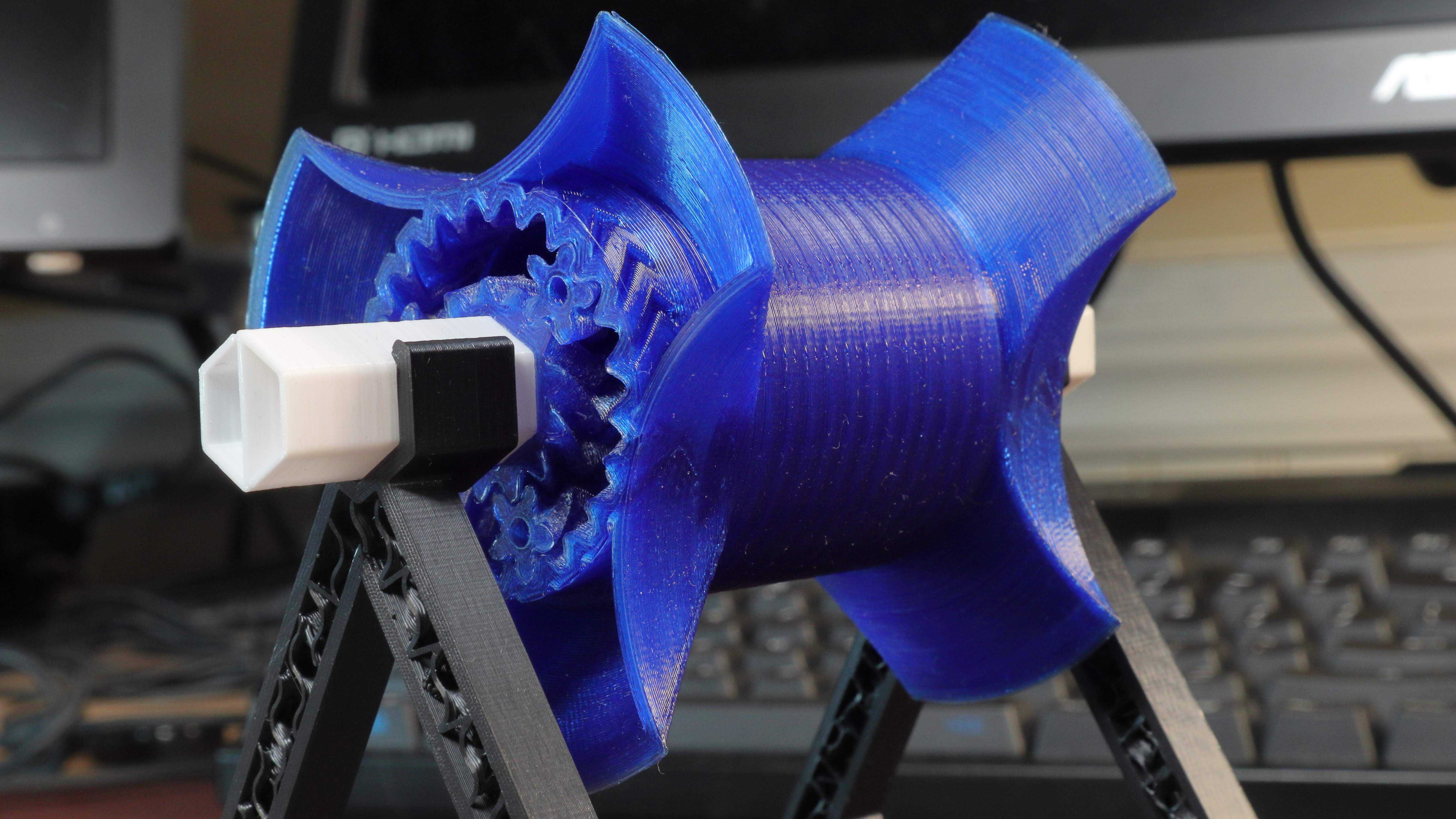
The spool hub incorporates print-in-place double helical (herringbone) planetary gear bearings at each end of the hub. A fixed axle fits through the sun gears about which the rest of the spool hub rotates. The fixed axle itself is a compliant spring to provide some resistance to axial sliding of the hub.
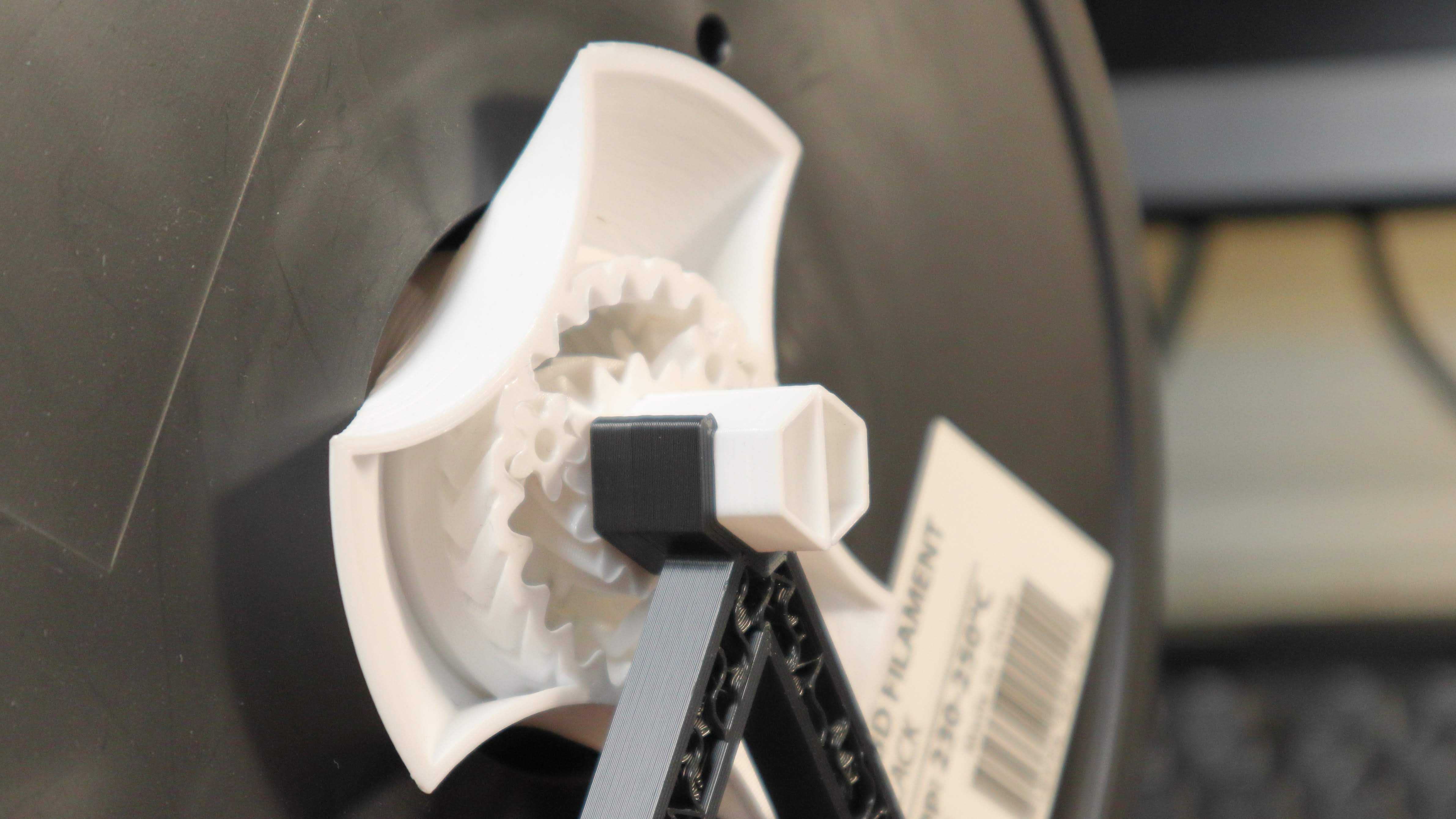
Printing spheres with FFF is problematic so, gears rather than balls offer a more fitting basis for rotary bearing design. Among the first things I printed after calibrating my printer was the iconic gear bearing design by emmitt, which expanded my understanding of the types of mechanisms that are 3D printable. I’m not sure which I stumbled onto first, but I was also inspired by the Helical Gear Generator plugin for Fusion 360 and this particular Gear Down for What? video.
The spool hub’s integrated, print-in-place bearing is a good example of a design element that Fused Filament Fabrication and similar additive manufacturing processes offer that traditional subtractive processes do not. It is still unreasonably satisfying each time I pull this print off of the bed and break loose the gears to reveal a functioning rotary bearing.
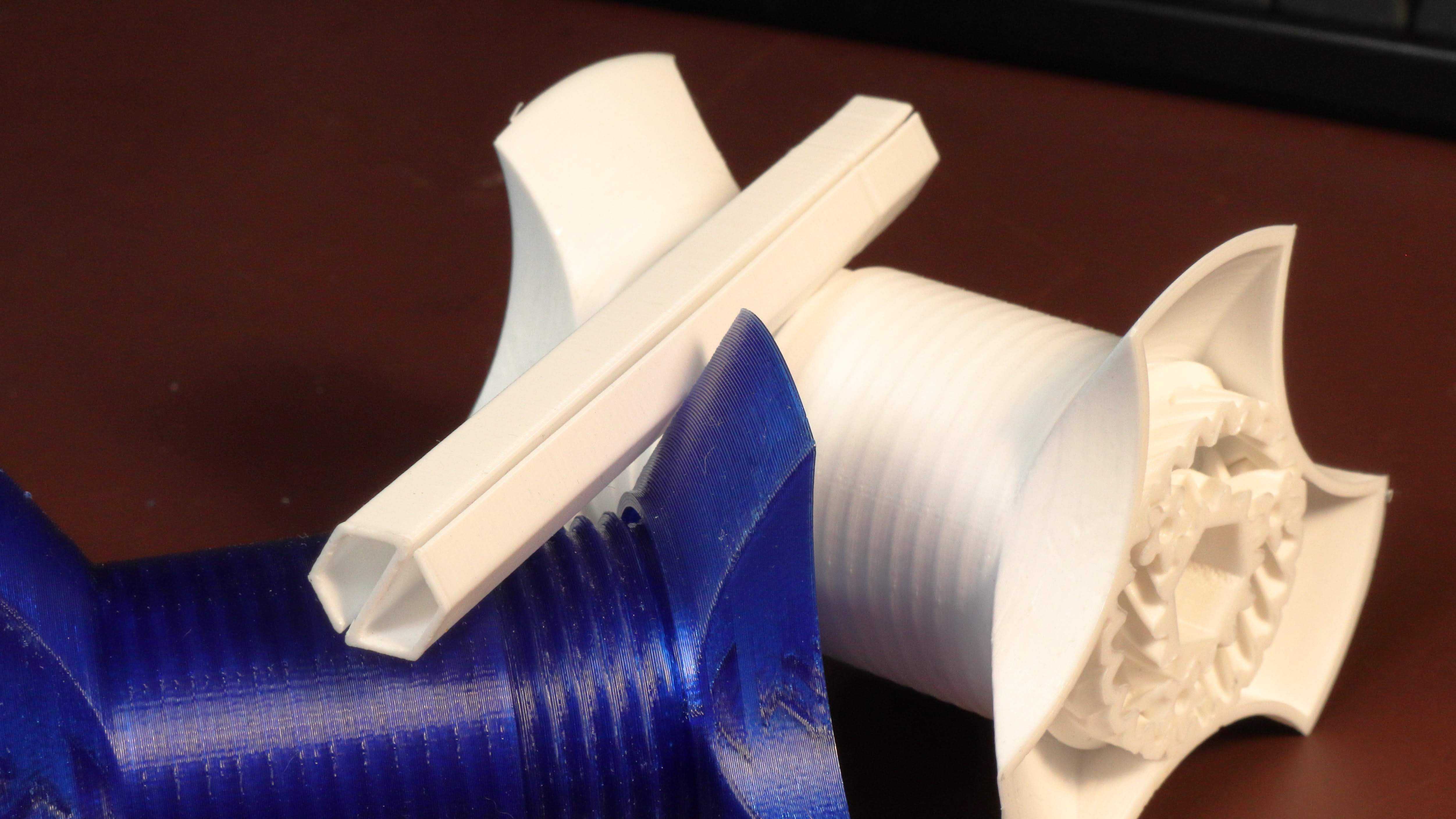
The fixed, spring-axle has a sort of “S”-shaped cross-section that is slightly larger than the hexagonal hole in the middle of the sun gear. Compressing the sides of the axle closes the gap and allows the axle to slide through the sun gear but provides some resistance as it pushes back toward its original shape. The geometry of the spring-axle allows it to be printed on end in vase mode relatively quickly.
Takeaways
More than a few iterations of every part of this design were required to get to its current state — the number of gears in the bearings, their thickness, the spool flange angle, the shape of the finger holds, the thread geometry and fixed-axle profile are just a few of the elements that were refined through many design-print-test cycles. However, what was surprising was the ease with which the very initial design concepts were translated into physical, working parts. As a mechanical engineer and long-time maker, there is something special about the ability to click Print on a “drawing” and watch your ideas materialize from a spool of plastic.